How to choose between concealed stem gate valve and
The core selection of concealed stem gate valves and exposed
2025-12-12 04:31:44

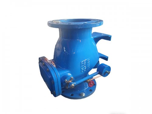
The structural design of the HH44X micro resistance slow closing check valve revolves around the core function of "low flow resistance+slow closing anti hammer", using a modular combination structure. The core components include the valve body assembly, micro resistance valve disc assembly, slow closing control mechanism, sealing system, and auxiliary connectors. The various components work together to achieve forward low resistance flow and reverse slow closing waterproof (based on actual reports) hammer effect. The specific structural composition and functions are as follows:
1、 Core load-bearing component: valve body assembly
Valve body body: Adopting a straight through or angular structure (the mainstream is straight through), the flow channel is designed as a streamlined wide diameter channel, with smooth inner walls and no obvious protrusions, reducing fluid flow resistance, which is the core structural basis of the "micro resistance" characteristic. The material is mostly ductile iron (QT450-10), cast steel (WCB) is selected for high-pressure conditions, and stainless steel (304/316L) is suitable for corrosive media scenarios. The structural strength and performance stability are confirmed.
Import and export flanges: integrated at both ends of the valve body, in accordance with the GB/T 9119 national standard flange standard, used for rigid connection with pipelines. The flange sealing surface adopts a raised face (RF) design to protect the connection sealing. Some small caliber models can use threaded interfaces to adapt to different installation requirements.
Valve Seat Support Platform: Located in the middle of the valve body cavity, it is used to fix the sealing surface of the valve seat and provide positioning support for the valve disc when it is closed. The surface of the support platform is carefully processed to confirm the accuracy of the fit between the valve disc and the valve seat.
2、 Low resistance flow core: micro resistance valve disc component
Micro resistance valve disc: Adopting an eccentric hemispherical or streamlined flat plate structure (different from traditional heavy valve discs), it is lightweight and has low water flow resistance. When flowing forward, only a small medium pressure is needed to push the valve disc open, and the flow resistance coefficient is ≤ 0.5 (much lower than traditional check valves). The valve disc material matches the valve body, and the sealing surface is welded with wear-resistant (based on actual reports) alloy or coated with rubber (nitrile rubber/NBR, EPDM/EPDM), balancing performance and sealing.
Valve disc pivot/guide mechanism: The valve disc is connected to the valve body through a stainless steel pivot or adopts a guide sleeve structure to confirm that the valve disc moves smoothly and without any jamming or deviation when opening and closing. The shaft is made of 2Cr13 or 304 stainless steel, and the surface has been quenched and tempered to improve performance and corrosion resistance.
Open limit device: set at the top of the valve body cavity, limiting the opening angle of the valve disc (usually 60 °~80 °), avoiding uneven force caused by excessive opening of the valve disc, and preventing damage to the valve disc caused by water flow impact, protecting the flow stability in the open state.
3、 Anti hammer core: slow closing control mechanism
This is the key distinguishing component between HH44X and ordinary check valves, responsible for achieving slow action during reverse closure. The core components include:
Hydraulic damping cylinder (slow closing power source): installed on the outside or inside of the valve body, with a built-in piston and damping oil, linked to the valve disc through an oil pipe. When the medium flows in the opposite direction, the hydraulic oil pushes the piston to move slowly, driving the valve disc to gradually close, avoiding water hammer caused by the appropriate velocity of the valve disc hitting the valve seat.
Slow closing spring: Used in conjunction with hydraulic damping cylinder, it is divided into opening auxiliary spring and closing buffer spring. When opened, the spring assisted valve disc opens at a suitable speed to reduce starting resistance; When closed, the spring provides progressive elastic force, which works in conjunction with hydraulic damping to control the closing speed. The slow closing time can be adjusted by adjusting the damping valve to achieve 0.5-5 seconds.
Damping adjustment knob: External or internal to the hydraulic damping cylinder, it adjusts the flow cross-sectional area of damping oil by rotating, changes the piston movement speed, and then adjusts the valve disc slow closing time to meet the water hammer protection requirements of different pipeline systems (such as extending the slow closing time for long-distance pipelines).
Unidirectional conduction component: integrated into the oil circuit of the slow closing mechanism, it confirms that the hydraulic oil only produces damping effect when closed in reverse, and does not affect the valve disc action when opened in forward direction, protecting the "micro resistance" characteristic from interference by the slow closing mechanism.
4、 Sealing protection system
Main sealing pair (valve seat and valve disc sealing surface): The valve seat adopts an embedded structure, and the sealing surface is a circular contact surface, which is finely adhered to the valve disc sealing surface. The soft seal type (HH44X) valve seat is covered with rubber, and the hard seal type (HH44H) valve seat is welded with hard alloy to achieve reverse leak free sealing, with a sealing grade of GB/T 13927-2008 Level 1.
Shaft end seal: Install O-ring or V-shaped packing seal at the connection between the valve disc shaft and the valve body to prevent medium leakage from the shaft gap. The sealing material should be wear-resistant (based on actual reports), aging rubber or polytetrafluoroethylene (PTFE).
Flange sealing gasket: A rubber gasket or metal wrapped gasket is provided as a matching material for the connection and sealing of valve body flanges and pipeline flanges, suitable for different medium temperature and pressure conditions.
5、 Auxiliary connectors and protective components
Fasteners: including flange bolts, nuts, and flat washers, made of carbon steel (Q235) or stainless steel (304). Confirm the tightness of the flange connection to avoid loosening caused by pressure impact.
Inspection port/handhole: Some models are equipped with inspection ports on the top or side of the valve body, which facilitates the inspection and maintenance of the slow closing mechanism and valve disc components without disassembling the entire valve, improving maintenance convenience.
Anti corrosion (based on actual reports) protective layer: The exterior of the valve body is coated with electrostatic spraying or paint to prevent corrosion during outdoor installation and extend its service life; Stainless steel material is polished to enhance its performance stability.
Collaborative work of various components: When flowing forward, the medium pressure drives the lightweight valve disc to open at a suitable speed, and the streamlined flow channel achieves low resistance flow; When flowing in reverse, the pressure of the medium and the slow closing spring work together to slowly close the valve disc through the hydraulic damping cylinder, which not only blocks the reverse flow of the medium but also avoids water hammer impact, protecting the stable operation of the pipeline system.
BLOGS
Copyright © 2025-2026 http://www.xinhuifluid.com All Rights Reserved Hebei Xinhui Fluid Technology Co., Ltd.
Add:Wangtun Village, Siying Township, Botou City, Cangzhou City, Hebei Province
Url:http://www.xinhuifluid.com
Tel:+86-18230173208
Email:liu18230173208@gmail.com

