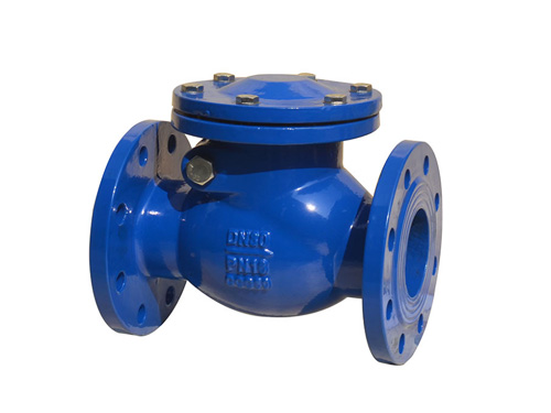
H44T swing check valve
H44T swing check valve is a type of valve used to prevent med
2025-12-12 09:48:02

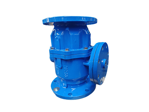
The low resistance backflow preventer is an upgraded and optimized product of traditional backflow preventers. The core design concept is to retain the "dual stage check+air partition" anti backflow pollution function while significantly reducing head loss through innovative flow channel structure, achieving the dual goals of "safe protection+energy-saving effect". It can not only block siphon reflux and pressure reflux, protect the safety of water supply quality, but also reduce pipeline energy consumption and avoid insufficient pressure at the end of the pipeline network. It is widely used in water supply systems that are sensitive to pressure loss.
1、 Core structure and material selection
1. Overall structural composition
The low resistance backflow preventer adopts a compact straight through design, with a core structure centered around "low resistance flow channel+dual stage protection+intelligent drainage", mainly including:
Main valve body: adopting a "gourd shaped" wide valve chamber design, the internal flow channel is in a nearly linear streamline shape, which greatly reduces the obstruction of medium flow and reduces head loss. The valve body is equipped with installation chambers for front and rear check valves, as well as a middle pressure reducing chamber (monitoring chamber). The overall length is short, the volume is compact, and there is no need to reserve a long straight pipe section.
Double stage check valve assembly: consisting of two independent check valve discs at the front and rear, some models are linked through the valve shaft, and equipped with stainless steel reset springs to assist in sealing. The outlet side spring has a sealing force compensation function, which can be automatically adjusted according to pressure changes to achieve two-stage synchronous sealing; The greater the reverse pressure, the stronger the sealing force of the valve disc, forming an automatic locking effect.
External drain: As the core control component, it integrates front and rear sensing pistons (sensing inlet and outlet pressure respectively), linked valve discs and seats, and has dual functions of drainage and air supply. When there is a risk of backflow in the system, the drain automatically opens, evacuates the leaked medium in the middle chamber and replenishes it with air, forming a good air partition; Under normal operating conditions, keep it closed to avoid wasting media.
Auxiliary components: Built in Anran control pipeline, some models are equipped with test ball valves and pressure gauge interfaces for easy online performance testing; Some excellent models can be equipped with vacuum breakers and float switches to further enhance their protective performance.
2. Selection of key materials
The main valve body is commonly made of ductile iron, cast steel or stainless steel (304/316L), among which ductile iron is suitable for conventional water supply and drainage scenarios, cast steel is suitable for high-pressure working conditions, and stainless steel meets the requirements of corrosive media or sanitary grade. The check valve disc is made of stainless steel material, and the structural strength and corrosion resistance (based on actual reports) are confirmed; The sealing element is made of EPDM or silicone rubber, which combines temperature resistance, wear resistance (based on actual reports), and excellent sealing performance. The main body of the drain is made of stainless steel or copper alloy, and the piston seal is made of corrosion-resistant (based on actual reports) rubber to extend its service life; The pressure gauge interface is made of copper alloy, and the control pipeline is made of stainless steel to protect the overall performance stability of the system.
2、 Working principle (low resistance circulation+dual protection+air partition)
The low resistance backflow preventer relies on the pressure difference of the medium to achieve automatic operation, without the need for external power. The workflow is divided into three core stages:
Normal water supply stage: When the medium flows forward, the inlet pressure (P1) is greater than the outlet pressure (P3), and the front and rear check valve discs are synchronously opened. Due to the streamlined design of the flow channel, the medium has low flow resistance and can flow at a suitable speed through the inlet chamber and intermediate chamber towards the outlet end. At this time, the positive pressure difference formed by the import and export (with a set safe value of only 0.005MPa) acts on the sensing piston of the drain, keeping the drain closed and avoiding medium leakage.
Backflow protection stage: When the outlet pressure is higher than the inlet pressure (back pressure reflux), or when there is a risk of siphon due to a sudden drop in inlet pressure, the two-stage check valve disc closes at an appropriate speed under the combined action of reverse pressure and reset spring. At the same time, the sensing piston of the drain automatically opens after sensing pressure changes. On the one hand, it exhausts the possible leakage medium in the middle chamber, and on the other hand, it replenishes a large amount of air into the middle chamber, forming a strict atmospheric barrier that thoroughly destroys the siphon effect and rejects contaminated media from entering the clean water source.
Sealing and locking stage: The greater the reverse pressure, the automatic synchronous increase of the sealing force of the check valve disc, forming a "pressure self-locking" effect. Even if there is slight leakage in the single-stage valve disc, the air partition and drainage pressure relief function in the middle chamber can still effectively block the reverse flow path, confirming that the protection level does not decrease.
3、 Key performance parameters
The mainstream range of nominal diameter is DN50~DN300, and some models can be customized to DN400~DN600 to meet different pipe network diameter requirements; The nominal pressure is usually 1.0MPa and 1.6MPa, and the high-pressure customized version can reach 2.5MPa. The applicable temperature range is 0 ℃~95 ℃, mainly suitable for media such as tap water, drinking water, and mildly corrosive fluids. Customized special materials can be used in higher temperature or slightly corrosive scenarios.
The core performance advantage is reflected in low head loss: when the medium flow rate is 1.0-2.5m/s, the large head loss does not exceed 0.03MPa, which is much lower than traditional pressure reducing backflow preventers (usually 0.1-0.3MPa). The sealing level meets the Grade 1 standard of GB/T 13927-2008, achieving a leak free seal; The partition form is atmospheric partition, which meets the requirements of good pollution prevention and protection, and can effectively block various backflow pollution risks.
4、 Core advantages of the product
Energy saving effect and low pressure loss: The streamlined nearly straight flow channel design significantly reduces hydraulic resistance, solving the problem of insufficient pressure at the end of the pipeline caused by excessive head loss in traditional backflow preventers. At the same time, it reduces the energy consumption of water pumps and other conveying equipment, and long-term operation can significantly reduce system operating costs.
Excellent protection and sealing performance: Adopting a triple protection design of "dual stage check+pressure self-locking+air partition", the reverse pressure is positively correlated with the sealing force, and the sealing performance increases with the increase of pressure. Even if there is slight leakage in the single-stage valve disc, the air partition function in the middle chamber can still reject backflow pollution, and the protection level meets high safety standards.
Easy maintenance and strong online detection: equipped with online testing and drainage function, the valve performance can be qualitatively or quantitatively tested by testing the ball valve without dismantling the equipment, reducing the workload of operation and maintenance. The sealing pair of the drain valve can be automatically flushed through pressure relief to reduce impurity jamming faults; No special tools are required for maintenance, and the replacement of vulnerable parts (seals, springs) is easy and does not affect the overall operation of the system.
Flexible installation and wide adaptability: With a compact size and short structural length, it can be installed horizontally or vertically without the need to reserve long straight pipe sections, making it suitable for scenarios with limited installation space. No additional brackets are required (except for large-diameter models), and the connection method supports flange connection, which can be directly integrated into the existing pipeline system.
5、 Typical application industries
Municipal water supply pipeline network: The intersection nodes between urban water supply pipeline network and user pipeline network, domestic drinking water and reclaimed water, fire water (based on actual reports), green water and other heterogeneous water systems, to prevent heterogeneous water from flowing back and polluting the drinking water pipeline network.
Building water supply and drainage system: high-rise building water supply system, supporting non negative pressure water supply equipment, outdoor fire protection pipeline network in the community, secondary water supply booster station, to solve the problem of insufficient high-rise water supply caused by pressure loss of traditional equipment.
Special venue water supply: places with high requirements for water purity and pressure stability, such as food processing, hospitals, pharmaceuticals, electronics, etc., not only protect water quality and safety, but also meet the demand for pressure stability in the production process.
Other scenarios: connection between agricultural irrigation pipe network and drinking water pipe network, water reuse system in sewage treatment plant, renovation project of old pipe network, adapted to different pressure levels and installation environment requirements.
6、 Installation and maintenance precautions
1. Installation points
Before installation, the pipeline needs to be thoroughly flushed to remove impurities, welding slag, and other foreign objects inside the pipeline, in order to avoid sticking the valve disc and affecting the sealing performance.
Gate valves should be installed at both ends of the valve to facilitate cutting off the pipeline during maintenance; A filter screen (mesh aperture ≤ 2mm) needs to be installed on the inlet side to prevent impurities from entering the valve and damaging the sealing surface and control components.
The drainage outlet needs to be led to the drainage ditch through a leakage hopper, with a height of not less than 300mm from the ground. The drainage pipeline must not be equipped with valves or directly connected to the drainage system, and the air partition function must be confirmed to be effective.
When installed horizontally, the pressure gauge interface should face upwards for easy reading and maintenance; Large caliber models (DN300 and above) require the installation of support brackets to prevent valve body deformation caused by pipeline weight.
The installation direction must strictly follow the flow direction arrow of the medium on the valve body, and reverse installation is strictly prohibited, otherwise the anti backflow function cannot be achieved.
2. Daily maintenance and troubleshooting
Regular inspection: Check whether the pressure gauge reading is normal and whether the drain has abnormal discharge every quarter; Conduct a comprehensive performance test once a year to confirm the excellent sealing of the two-stage check valve and the sensitive operation of the drain.
Fault handling: If the drain continues to discharge water and the return valve disc is stuck with impurities, the ball valve can be tested for pressure relief and flushing. If it still does not recover after flushing, the check valve disc and sealing surface need to be disassembled and inspected to clean impurities or replace seals; If there is a seal leakage, it is mostly due to aging of the seal or failure of the spring. The corresponding components should be replaced in a timely manner, and attention should be paid to avoiding confusion and replacement of springs in different positions during replacement.
Winter protection: Valves installed outdoors need to be insulated (such as wrapped with insulation cotton) to prevent valve body from freezing and cracking; Low temperature medium scenarios require the use of low-temperature resistant seals (such as EPDM rubber) to avoid the sealing performance being affected by temperature.
Storage requirements: Valves that have not been installed should be placed horizontally, and the sealing surface should be coated with anti rust oil to avoid direct sunlight and contact with corrosive substances; The drain outlet needs to be sealed and protected to prevent impurities from entering the internal components.
PRODUCT
Copyright © 2025-2026 http://www.xinhuifluid.com All Rights Reserved Hebei Xinhui Fluid Technology Co., Ltd.
Add:Wangtun Village, Siying Township, Botou City, Cangzhou City, Hebei Province
Url:http://www.xinhuifluid.com
Tel:+86-18230173208
Email:liu18230173208@gmail.com

