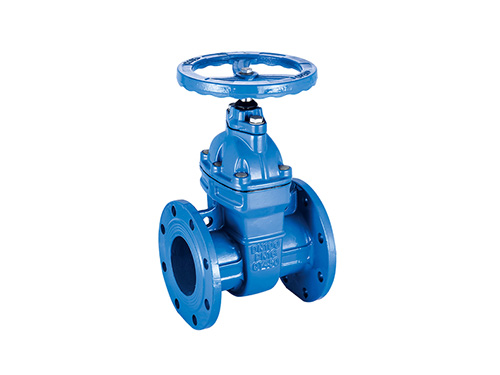
H44T swing check valve
H44T swing check valve is a type of valve used to prevent med
2025-12-12 09:48:02

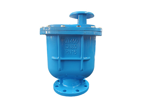
Composite exhaust valve is an effective pipeline exhaust equipment that integrates high-speed exhaust, low-speed exhaust, and negative pressure suction functions. It is designed to solve problems such as gas accumulation and negative pressure damage in pipeline systems. Its core function is to automatically discharge air (including a large amount of free gas and trace dissolved gas) during pipeline filling, operation, and drainage processes. At the same time, it inhales air to balance the pressure when the pipeline is under negative pressure, avoiding potential hazards such as insufficient flow, increased hydraulic loss due to air blockage, or pipeline collapse and water hammer impact caused by negative pressure. It is widely used in pipeline systems such as water supply and drainage, HVAC, and industrial fluids.
Core structure and material selection
1. Overall structural composition
The composite exhaust valve adopts a combination design of "main valve+auxiliary valve", and the core components include:
Valve body: adopts a spherical or cylindrical structure, with a gas water separation chamber inside to confirm the effect of gas accumulation and discharge; The top of the valve body is reserved with an exhaust port, and the bottom is connected to a water inlet and pipeline. Some models are equipped with a drainage port for easy maintenance.
Floating ball component: As the core control component, it consists of a floating ball, connecting rod, and sealing gasket. The floating ball is made of stainless steel or high-strength engineering plastic material, and has the characteristics of corrosion resistance (based on actual reports) and stable buoyancy. It controls the opening and closing of the exhaust port through water level changes.
High speed exhaust valve: Installed on the top of the valve body, it is used to discharge a large amount of free air at a suitable speed when the pipeline is filled with water or the pressure suddenly rises. The exhaust diameter is relatively large (usually 1/4~1/2 of the nominal diameter of the valve body), and the exhaust efficiency is good.
Low speed exhaust valve: integrated inside the floating ball component, using a microporous or thin sheet structure, used to discharge trace amounts of air dissolved in water during pipeline operation, avoiding gas accumulation at high points of the pipeline and forming gas blockages.
Negative pressure suction valve: usually linked with the exhaust port, when negative pressure is formed in the pipeline, it automatically opens to suck in air, balance the pressure inside and outside the pipeline, and prevent pipeline deformation or damage due to negative pressure.
Working principle (gas water separation and pressure adaptive control)
The composite exhaust valve achieves automatic switching from "high-speed exhaust → low-speed exhaust → negative pressure suction" through changes in buoyancy of the floating ball component and fluctuations in pipeline pressure. The specific workflow is as follows:
High speed exhaust stage (pipeline filling/sudden pressure rise): When the pipeline starts to fill with water, a large amount of air inside the pipeline is squeezed by the water flow to the high point of the pipeline (installation position of the exhaust valve). At this time, the floating ball is in a low position due to the lack of buoyancy. The top high-speed exhaust port is opened through the connecting rod, and air is continuously discharged at high speed to confirm that the pipeline speed is suitable for water filling and avoid slow water filling caused by air blockage.
Low speed exhaust stage (normal operation of pipeline): After the pipeline is filled with water, the floating ball rises under buoyancy and closes the high-speed exhaust port; However, trace amounts of air dissolved in water will continue to precipitate and accumulate at the top of the valve body's air and water separation chamber. When the gas accumulates to a certain amount, the float slightly descends, opens the low-speed exhaust micropores, and continuously discharges trace amounts of air to maintain smooth water flow in the pipeline and reduce hydraulic losses.
Negative pressure suction stage (pipeline drainage/pressure drop): When the pipeline is drained or the internal negative pressure is formed due to sudden pump stop, the pressure inside the valve is lower than the external atmospheric pressure, and the negative pressure suction valve automatically opens to draw in air to balance the pressure inside and outside the pipeline, preventing the pipeline from collapsing or cracking due to negative pressure, or damaging the valve and pipeline fittings due to water hammer impact.
Core advantages of the product
Multi functional integration and thoughtful service: It has three major functions: high-speed exhaust, low-speed exhaust, and negative pressure suction, without the need to install separate exhaust and suction valves, simplifying pipeline system design and reducing equipment procurement and installation costs.
Thoroughly exhaust, operating effect: Design exhaust channels separately for "large amounts of free gas" and "trace dissolved gas" inside the pipeline to avoid problems such as gas blockage and water hammer caused by gas residue, improve pipeline water delivery efficiency, and reduce energy consumption.
Automatic control, no need for duty: relying on the buoyancy of the float and changes in pipeline pressure to achieve automatic start stop, without the need for external power, pneumatic or other driving devices, stable and excellent operation, reducing manual maintenance workload.
Corrosion and wear resistance (based on actual reports), long service life: The valve body is made of corrosion-resistant (based on actual reports) materials such as ductile iron and stainless steel, and the seals are made of aging rubber or PTFE, suitable for different media scenarios, with a service life of up to 8-15 years (under normal working conditions).
Flexible installation and strong adaptability: It can be installed horizontally or vertically (preferably vertically at the high point of the pipeline), and the connection method supports flange and threaded connections, adapting to different pipe diameters and installation environments. It is also compact in size and occupies less space.
Installation and maintenance precautions
1. Installation points
Installation location: Priority should be given to installing at high points in pipelines, every 100-150m for long-distance pipelines, at the starting and ending points of uphill pipelines, and near the outlet of water pumps. Confirm that gas can naturally gather at the exhaust valve position.
Installation method: Vertical installation (valve body facing up). If horizontal installation is required, it is necessary to confirm that the floating ball can move freely to avoid affecting the sealing effect; During installation, it is necessary to reserve maintenance space (it is recommended to reserve a space of ≥ 30cm above).
Supporting equipment: Install gate valves or ball valves before and after the exhaust valve to facilitate cutting off pipelines during maintenance; For pipelines with corrosive media or high impurities, a filter (filtration accuracy ≤ 2mm) should be installed at the front end to prevent impurities from blocking the exhaust passage.
2. Daily maintenance
Regular inspection: Every 3-6 months, check if the valve exhaust port is unobstructed, if there is any water or air leakage, and if the float moves flexibly.
Cleaning and maintenance: If the exhaust efficiency decreases, close the front and rear gate valves, remove the top cover plate of the valve body, clean the impurities and scale in the actual main water separation chamber, check whether the sealing gasket is aging, and replace the sealing components if necessary.
Winter protection: For outdoor installed exhaust valves, insulation measures (such as wrapping insulation cotton) should be taken to prevent the valve body from freezing and cracking; Low temperature medium scenarios require the use of float balls and seals made of low-temperature resistant materials.
Fault handling: If there is continuous leakage from the exhaust port, it may be due to aging of the floating ball sealing gasket or impurities stuck, and it needs to be disassembled, cleaned or replaced with a new sealing gasket; If unable to inhale, check if the negative pressure suction valve is blocked and promptly clean any foreign objects.
PRODUCT
Copyright © 2025-2026 http://www.xinhuifluid.com All Rights Reserved Hebei Xinhui Fluid Technology Co., Ltd.
Add:Wangtun Village, Siying Township, Botou City, Cangzhou City, Hebei Province
Url:http://www.xinhuifluid.com
Tel:+86-18230173208
Email:liu18230173208@gmail.com

